- E-Mail-Adresse
- Telefon
-
Adresse
158 Chengshi Road, Lili Town, Wujiang District, Suzhou
Produktkategorien
Hengtai Synthesis Instrument Instrument Manufacturing (Suzhou) Co., Ltd.


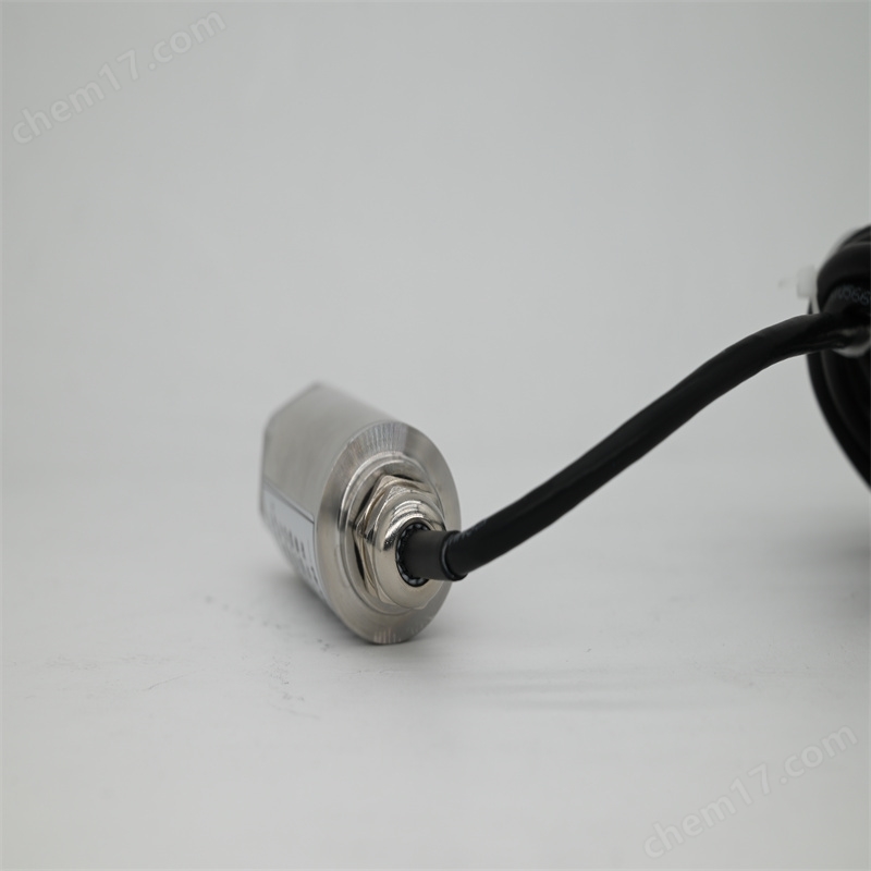
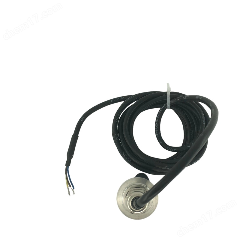
Integrierter Feldtransfer Vibrationsmesssensor JMB35L
VerhandlungsfähigAktualisieren am05/15
- Modell
- Natur des Herstellers
- Hersteller
- Produktkategorie
- Ursprungsort
Übersicht
Integrated Field Ventilator Vibration Measurement Sensor JMB35L, Field Ventilator Vibration Measurement Sensor JM-B-35L integriert einen Schwingungsgeschwindigkeitssensor und eine präzise Messschaltung zusammen, um eine hochpräzise Schwingungsmessung zu bilden. ..
Produktdetails
Integrierter Feldtransfer Vibrationsmesssensor JMB35L
JM-B-35L integriert den Schwingungsgeschwindigkeitssensor und die Präzisionsmessschaltung zusammen, um ein hochpräzises Schwingungsmesssystem zu bilden, das die Funktion des traditionellen "Sensor + Überwachungsinstrumentmodus des Schwingungsmesssystems erreicht, der Sender kann direkt mit DCS, SPS oder anderen Geräten verbunden werden, ist die ideale Wahl für die Schwingungsmessung von Fabrikgeräten wie Lüftern, Motoren, Wasserpumpen und anderen.
Technische Parameter
Stromversorgung: 24VDC ± 10%
Eingangssignal: Signal vom integrierten Schwingungsgeschwindigkeitssensor
Empfindlichkeit: 20mv/mm/s ± 5%
Frequenzreaktion: 10 bis 1000 Hz oder 5 bis 1000 Hz (spezielle Anweisungen)
Messbereich: 0-20 mm/s (wirklicher Wert)
0-200um (Spitze-Spitze)
Messfehler: ±1% voller Messbereich
Ausgangsstrom: 4-20mA
Ausgangswiderstand: ≤500Ω
Temperaturbereich: Betriebszeit: -25 ℃ ~ 65 ℃
Lagerung: -40 ℃ ~ 85 ℃
Relative Luftfeuchtigkeit: bis zu 95%, ohne Kondensation
Größe: φ33 × 75mm
Gewicht: ca. 340g
Bestellnummer
XJ-9200A □□ (optional) - □□ (V / D) - A □□ - B □□ - C □□
Auswahl Beschreibung
Optional: Wasserdichte Verbindungen □: F-Wasserdichte Verbindungen
Kai-Montage-Ausgang□: B-Kai-Montage-Rohr
Optional: Auswahl
Messbereich □□:
Schwingungsgeschwindigkeit 10V-0 ~ 10mm / s; 20V*-0~20mm/s; 30V-0~30mm/s; ……
Schwingungsverschiebung 100D-0 bis 100μm; 100D-0~200μm; 300D-0~300μm; ……
Installationsrichtung A:
1. Ebene; 2. Vertikal; 3* - Allgemein
Einbauschraube B□:
1*-M10×1.5; 2-M8×1.25; 3. Magnetisch; 4. Spezielle Anpassungen
Kabellänge C:
1-1m; 2*-2m; 3-3m; ……
Keine Sonderfälle, Hersteller nach Artikel produzieren; Bei besonderen Wünschen wenden Sie sich bitte an unser Unternehmen.
Ausführungsbeispiel: XJ-9200A-20V-A3-B1-C2
Schwingungsmesssensor JM-B-35L


Technische Parameter
Stromversorgung: 24VDC ± 10%
Eingangssignal: Signal vom integrierten Schwingungsgeschwindigkeitssensor
Empfindlichkeit: 20mv/mm/s ± 5%
Frequenzreaktion: 10 bis 1000 Hz oder 5 bis 1000 Hz (spezielle Anweisungen)
Messbereich: 0-20 mm/s (wirklicher Wert)
0-200um (Spitze-Spitze)
Messfehler: ±1% voller Messbereich
Ausgangsstrom: 4-20mA
Ausgangswiderstand: ≤500Ω
Temperaturbereich: Betriebszeit: -25 ℃ ~ 65 ℃
Lagerung: -40 ℃ ~ 85 ℃
Relative Luftfeuchtigkeit: bis zu 95%, ohne Kondensation
Größe: φ33 × 75mm
Gewicht: ca. 340g
Bestellnummer
XJ-9200A □□ (optional) - □□ (V / D) - A □□ - B □□ - C □□
Auswahl Beschreibung
Optional: Wasserdichte Verbindungen □: F-Wasserdichte Verbindungen
Kai-Montage-Ausgang□: B-Kai-Montage-Rohr
Optional: Auswahl
Messbereich □□:
Schwingungsgeschwindigkeit 10V-0 ~ 10mm / s; 20V*-0~20mm/s; 30V-0~30mm/s; ……
Schwingungsverschiebung 100D-0 bis 100μm; 100D-0~200μm; 300D-0~300μm; ……
Installationsrichtung A:
1. Ebene; 2. Vertikal; 3* - Allgemein
Einbauschraube B□:
1*-M10×1.5; 2-M8×1.25; 3. Magnetisch; 4. Spezielle Anpassungen
Kabellänge C:
1-1m; 2*-2m; 3-3m; ……
Keine Sonderfälle, Hersteller nach Artikel produzieren; Bei besonderen Wünschen wenden Sie sich bitte an unser Unternehmen.
Ausführungsbeispiel: XJ-9200A-20V-A3-B1-C2
Schwingungsmesssensor JM-B-35L
Zusammensetzung und Prinzip des Druckübertragungssystems
DruckSenderEs handelt sich um eine Ausgabe zur Standardisierung.SignalederDrucksensorStandardisiertes Signal bezieht sich auf ein Signal, das sowohl in Form als auch im Wertbereich der physikalischen Größe international standardisiert ist. zum BeispielsimulierenGleichstromStrom4-20mA、 Der Gasdruck von 20 bis 100 kPa ist ein weit verbreitetes Standardsignal. Darüber hinaus verwenden inländische Drucksender manchmal einen Gleichstrom von 0-10mA als Ausgangssignal. Unabhängig von der physikalischen, chemischen oder biologischen Eingangsvariable des DruckgebersParameterUnabhängig von der Größe des Eingangssignals, nach dem SenderInformationAlles muss im Standard-Signal enthalten sein. Durch die einheitliche Ausgangssignalform und den Wertbereich ist es einfach, Drucksender und andere Messgeräte zusammenzustellenErkennungSysteme oder Regulierungssysteme. Unabhängig davon, welches Gerät oder welches Gerät, solange die gleiche Standard-Eingangsschaltungsschnittstelle vorhanden ist, kann die Ausgangsinformation des Druckgebers erhalten werden und somit Informationen über die Eingangsvariablen des Druckgebers erhalten werden. Einheitliche Ausgangssignalstandards für Drucksender verbessern die Kompatibilität und Austauschbarkeit des gesamten Systems und ermöglichen eine einfache Bedienung.
1. Systemdiagramm
Die wichtigsten Komponenten des Kalibriersystems sindObere MaschineHardware-Schaltung, DruckSteuerungMehrwertige Uhren usw. Über vier 232-serielle Anschlüsse ermöglicht der obere Gerät die Verbindung zu unteren Geräten, Druckgebern, Mehrzweckzählern und DruckreglernKommunikationNach der Installation des automatischen Kalibrierungssoftwaresystems auf der oberen Maschine kann die automatische Kalibrierung des 32-Wege-Drucksenders erfolgen. Die Hardwareschaltung der unteren Maschine ist mit der oberen Maschine über den seriellen Anschluss 232 verbunden und steuert den freien Umschalt der 32-Wege-Kalkulationskanäle. Das Protokollumwandlungsmodul des unteren Maschinenteils ermöglicht die Kommunikation zwischen der oberen Maschine und dem Druckgeber. Der Druckregler kommuniziert über den seriellen Anschluss 232 mit dem Obergerät, empfängt Druckregelinformationen und steuert die Eingangsluftdruckgröße des Druckgebers. Das Multimeter kommuniziert über den seriellen Anschluss 232 mit dem Obergerät und empfängt die Steuerinformationen des Multimeters, um die erfassten Ausgangsstromdaten des Drucksenders an den Obergerät zu senden.
2. Definitionsprinzip
Automatisches Kalibrierungssystem für DruckgeberStromversorgungDigitale Kalibrierung der Nullpunktmigration und der Rangmigration von Stromausgangsdruckgebern. Die Nullpunktmigration bezieht sich auf eine Änderung des Ausgangswertes des Drucksenders, wenn der Sender an der unteren Grenze des Arbeitsbereichs arbeitet. Die Messungsmigration bezieht sich auf die Veränderung des Stromausgangsbereichs des Drucksenders mit einem bestimmten Mittel. Das Prinzip der Kalibrierung des Druckübertragers besteht darin, den Standardwert des Druckübertragers in seinem Arbeitsbereich als Maßstab auszugeben, den Wert der ursprünglichen Ausgabe des zu kalibrierenden Druckübertragers in seinem Arbeitsbereich zu messen, um den Wert der Nullpunktmigration und -migration zu berechnen, die für den zu kalibrierenden Druckübertrager erforderlich ist, und die Berechnungsergebnisse in die Signalregulation innerhalb des Druckübertragers zu schreiben.ChipUm die Eingangs- und Ausgangskurve des zu kalibrierenden Druckgebers in seinem Arbeitsbereich im Einklang mit der Standard-Eingangs- und Ausgangskurve des Druckgebers zu erreichen, wird die Kalibrierung abgeschlossen.
Integrierter Feldtransfer Vibrationsmesssensor JMB35L
Ähnliches Produkt Empfehlen